Introduction
I am currently playing with a relatively standard Yocto distribution on my favorite SBC board of the moment, the NanoPi Neo. By hooking a cheap I²C 16×2 LCD screen on it, we can provide system feedback of our Linux system — but instead of going the easy way by doing everything in userspace, let's see what the Linux kernel has to offer in terms of driver support for such cheap screens.
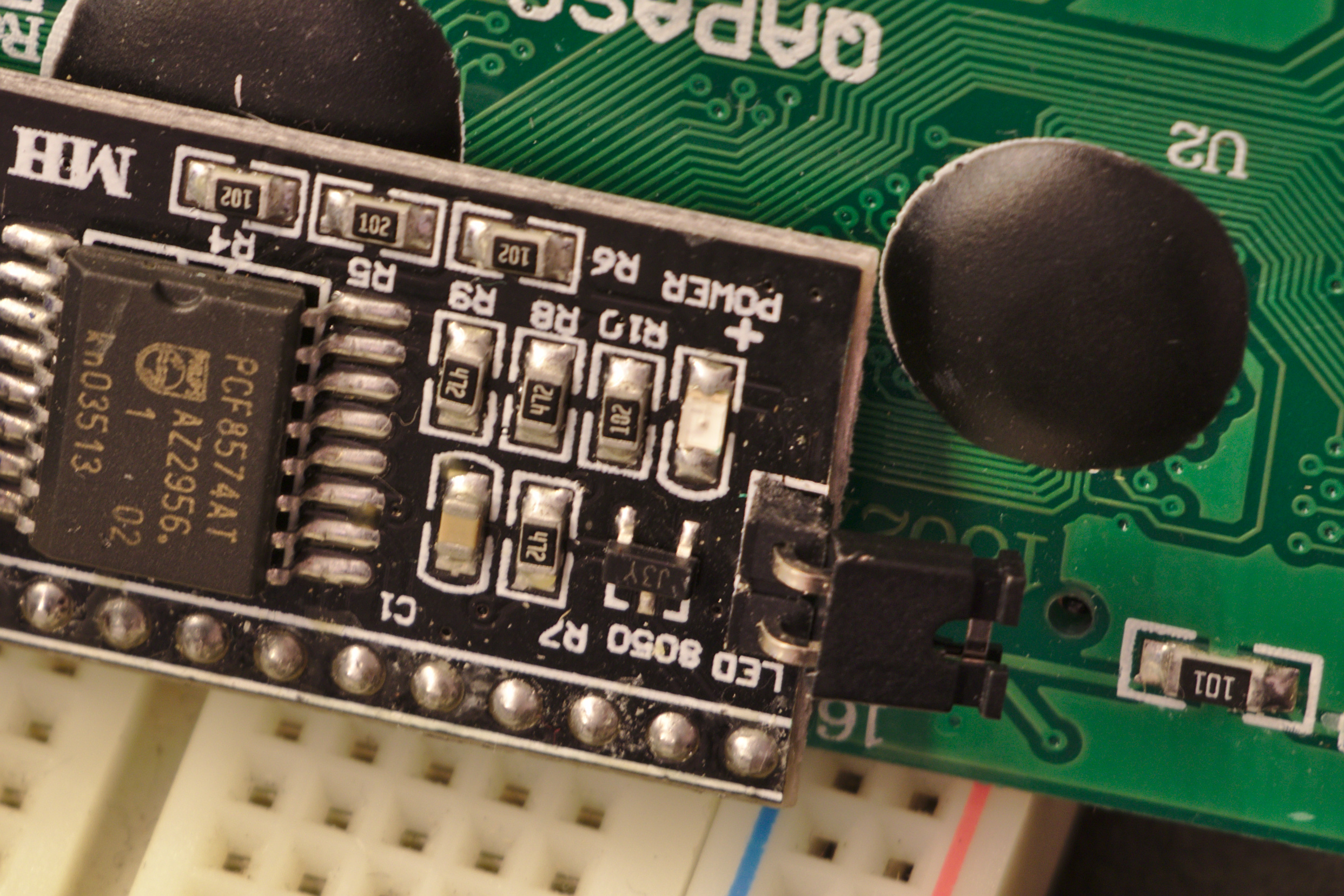
The HD44780 LCD screen used here is composed of 16 columns and 2 lines. This specific model has the particularity of being accessible by I²C, using a PCF8574A GPIO expander. You can see what it looks like and the prices on AliExpress (check also other vendors, this one was chosen only to illustrate with a nice picture).
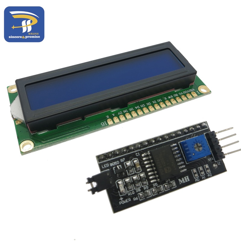
The screen I will be using looks like this one proposed on AliExpress.
This article will only focus on the hardware, the Linux kernel and some userspace code — the buildsystem based on Yocto I am using will not be detailed that much. If you know Yocto already, I am using meta-sunxi layer for this article.
Hooking the screen to the board
The original HD44780 screen is controlled using a parallel bus of 4 bits and some other control lines. Wiring the screen is often time consuming and error prone because 8 wires have to be correctly connected. This is why the screen I have ordered is provided with an I²C GPIO expander on its back. This reduces the number of wires to use between the SBC and the screen to only 4 of them :
- SCA (I²C data)
- SCL (I²C clock)
- GND
- VCC (+5 VDC)
The last one may however be a problem. As the NanoPi Neo is rated for 3.3 VDC input/output operations, this is incompatible with the 5 VDC required by the screen.
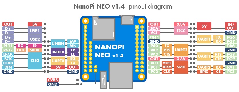
NanoPi Neo v1.4 pinout diagram (from the NanoPi Neo wiki). We will be using I²C0 bus.
Frying a few boards first…
The solution I first attempted to this voltage incompatibility problem was dumb: I hooked SCA, SCL and GND to the board, and then used the board's 5 V input (USB power-in) to power the screen too. This eventually worked for a few hours, before the NanoPi went dead silent and the SoC chip was blazingly hot permanently.
This toaster effect that I have experienced a lot of time during various hacks means that we have killed the board altogether and that it is good to go to the SBC cemetery that every hacker has constituted over time.
Did you guess what went wrong? Well, remember that I²C is quite interesting on the voltage side: it requires a pull-up on the SCA and SCL lines — so that when no data is transiting, both lines are held HIGH to VCC's voltage. Problem is, when checking with a multimeter, we can see that the pull-up is done on the screen side: we measure 5 V when no data is in transit. This means that with the current assembly, 5 V is going though the SBC's SCA and SCL pins. Not good.
This will eventually work for quite some time — as I have experienced before when we hooked I²C devices this way in my engineering school's robotic club — before the board would fry and become a mini-toaster (at that time, our cemetery was then constituted of 4 or 5 Raspberry Pi B+, first generation).
The solution: logic level converters
The solution to this problem is however simple: we need to put a level converter between the screen's SCA/SCL lines and the SBC's ones. This way, when the bus is idle, the screen sees 5 V on SCA and SCL, while the SBC sees 3.3 V. Same logical state for both components, but different voltages. When the line drops to 0 V during a bit transition when a frame is sent, well, both lines drop to 0 V so the logical level is also coherent.
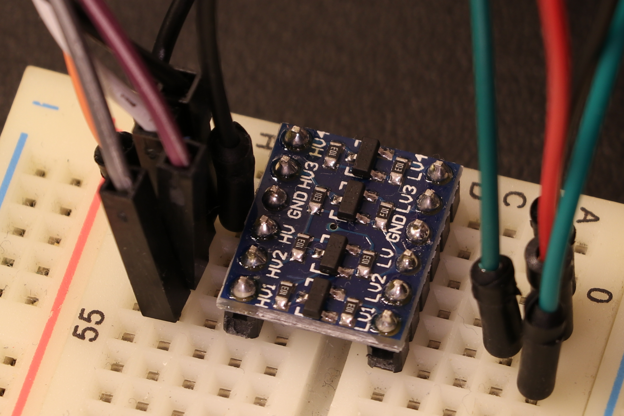
HV stands for high voltage (5 V in our case) and LV for low voltage (3.3 V).
As I did not want to cable some transistors on the breadboard — and as I was prudent by ordering a couple of cheap logic level converters online — I just plugged one in between the two voltage-incompatible components. The wiring is quite simple and self-explained on the PCB's silk screen layer.
Another solution I have tried is to power the screen with 3.3 V, so both VCC match. This is not really a good solution, though it kind of work. The screen is very dim as it has not enough voltage, but it can display characters. However, the reduced refresh rate of the liquid crystals and low brightness makes it too hard to read in good conditions — thus this idea was abandoned.
Just use level converters.
After the hardware, now comes the software
Now that everything is hooked up, let's try to display some characters on the screen. We will do it the Linux kernel way — instead of using an userspace library that would open /dev/i2c0 and do its stuff.
Activating the I²C bus
First, to access the /dev/i2c0 bus on the board, we need to activate it in the device tree. We will append the following block into the original sun8i-h3-nanopi-neo.dts reference device tree for the board found in <kernel>/arch/arm/boot/dts/ directory.
This is because by default, all of the available buses are declared in the SoC device tree, but it is to the discretion of the final user to activate one bus or another. Activating a bus may disable another one. For i2c0, we can see on the pinout diagram that this should not cause any issue, but activating uart1 will result in making the PG6 and PG7 GPIO unavailable.
&i2c0 {
    status = "okay";

    pcf8574a: i2c0@3f {
        compatible = "nxp,pcf8574a";
        reg = <0x3f>;
        gpio-controller;
        #gpio-cells = <2>;
    };
};
We can see that we also added the pcf8574a node in the i2c0 one. This is declaring our GPIO expander as a GPIO controller, using the address 0x3f on the i2c0 bus.
Finding the I²C address of the GPIO expander
In order to find the possible addresses, one could read the chip documentation to see possible values. Most of the time it consists of a base address to which we can add an offset. This offset can be set by soldering pull-up or pull-down resistors to some of the expander's pin — to allow multiple components of the same type to have different addresses.
Let's have a look at the datasheet of the component to find the address range of the device.
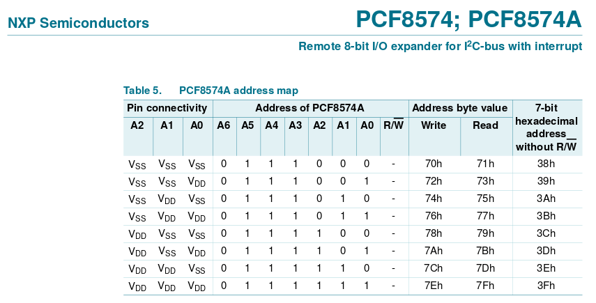
You want to look at the very last column to read the possible addresses.
Given that we can see (well, not photo for this one) that none of the configuration resistors are present on the SMD pads of the PCB, we can try our chance with all inputs low (0x71) or all inputs high (0x7f).
In fact, an easier way is to use the i2cdetect software on our SBC, which is part of i2cutils. It will probe all addresses to find out which slaves are present on the bus. Let's run it already!
root@nanopi-neo:~# i2cdetect 0
WARNING! This program can confuse your I2C bus, cause data loss and worse!
I will probe file /dev/i2c-0.
I will probe address range 0x03-0x77.
Continue? [Y/n]
     0  1  2  3  4  5  6  7  8  9  a  b  c  d  e  f
00:          -- -- -- -- -- -- -- -- -- -- -- -- --
10: -- -- -- -- -- -- -- -- -- -- -- -- -- -- -- --
20: -- -- -- -- -- -- -- -- -- -- -- -- -- -- -- --
30: -- -- -- -- -- -- -- -- -- -- -- -- -- -- -- UU
40: -- -- -- -- -- -- -- -- -- -- -- -- -- -- -- --
50: -- -- -- -- -- -- -- -- -- -- -- -- -- -- -- --
60: -- -- -- -- -- -- -- -- -- -- -- -- -- -- -- --
70: -- -- -- -- -- -- -- --
This confirms us that the device was found at address 0x3f.
Side note: I have myself submitted a patch to this software not so long ago, to probe devices that are outside of the allowed address ranges in the I²C specification. This was done in the context of work, where we use devices that are using out of range addresses like 0x02. It was a great experience to upstream this patch to the community.
Finding the GPIO pinout between the screen and the expander
Now that we have access to the I²C GPIO expander, we yet have to find out which GPIO on the expander is wired to which pin of the screen. We will have to provide this information into the device tree, as it is explained in the hit,hd44780.txt file in the kernel documentation.
I will copy it here, as it is short enough, and also because unused drivers and their documentation have the tendency to disappear in the kernel — and I fear that this driver may one day be removed because so many users prefer to use some userspace Python code or stuff to talk to this kind of device.
DT bindings for the Hitachi HD44780 Character LCD Controller

The Hitachi HD44780 Character LCD Controller is commonly used on character LCDs
that can display one or more lines of text. It exposes an M6800 bus interface,
which can be used in either 4-bit or 8-bit mode.

Required properties:
  - compatible: Must contain "hit,hd44780",
  - data-gpios: Must contain an array of either 4 or 8 GPIO specifiers,
    referring to the GPIO pins connected to the data signal lines DB0-DB7
    (8-bit mode) or DB4-DB7 (4-bit mode) of the LCD Controller's bus interface,
  - enable-gpios: Must contain a GPIO specifier, referring to the GPIO pin
    connected to the "E" (Enable) signal line of the LCD Controller's bus
    interface,
  - rs-gpios: Must contain a GPIO specifier, referring to the GPIO pin
    connected to the "RS" (Register Select) signal line of the LCD Controller's
    bus interface,
  - display-height-chars: Height of the display, in character cells,
  - display-width-chars: Width of the display, in character cells.

Optional properties:
  - rw-gpios: Must contain a GPIO specifier, referring to the GPIO pin
    connected to the "RW" (Read/Write) signal line of the LCD Controller's bus
    interface,
  - backlight-gpios: Must contain a GPIO specifier, referring to the GPIO pin
    used for enabling the LCD's backlight,
  - internal-buffer-width: Internal buffer width (default is 40 for displays
    with 1 or 2 lines, and display-width-chars for displays with more than 2
    lines).

Example:

        auxdisplay {
                compatible = "hit,hd44780";

                data-gpios = <&hc595 0 GPIO_ACTIVE_HIGH>,
                             <&hc595 1 GPIO_ACTIVE_HIGH>,
                             <&hc595 2 GPIO_ACTIVE_HIGH>,
                             <&hc595 3 GPIO_ACTIVE_HIGH>;
                enable-gpios = <&hc595 4 GPIO_ACTIVE_HIGH>;
                rs-gpios = <&hc595 5 GPIO_ACTIVE_HIGH>;

                display-height-chars = <2>;
                display-width-chars = <16>;
        };
So, we need to add this auxdisplay node in our device tree, and configure it with the pins of the PCF8574A (remember, we declared it as a gpio-controller just before).
For this, one could go with a multimeter to probe between the expander and the screen's pins to understand how it was designed. But this screen setup is so cheap and familiar in the maker community that the LiquidCrystalI2C Arduino library will be a great candidate for retro engineering out the pinout.
By digging into the code — which is not easy to the eyes after passing so much time reading the Linux driver code — we can identify the few defines that identify the screen's pins by numbers that are the number of the GPIO pin of the expander.
Here is the first part that will help us in this task, located in LiquidCrystal_I2C.h:
#define En B00000100  // Enable bit
#define Rw B00000010  // Read/Write bit
#define Rs B00000001  // Register select bit
And then the other part to look at is this send method in the LiquidCrystal_I2C.cpp file:
// write either command or data
void LiquidCrystal_I2C::send(uint8_t value, uint8_t mode) {
    uint8_t highnib=value&0xf0;
    uint8_t lownib=(value<<4)&0xf0;
    write4bits((highnib)|mode);
    write4bits((lownib)|mode);
}
We can see that the bits used for the data are the 4..7 bits, because the values highnib and lownib are bitwise-and masked with 0xf0 — which represent the top most 4 bits of a byte. This way, we can establish the following layout of the GPIO expander to the screen from our retro engineering of the library:
| Pin number (GPIO expander) | 7 | 6 | 5 | 4 | 3 | 2 | 1 | 0 |
| Pin name (screen) | D3 | D2 | D1 | D0 | BL | EN | RW | RS |
We can then add the screen to the root of the SBC's device tree — because there is no reason to put it under the GPIO expander — and then configure the screen entry to use the expander's pins [1].
auxdisplay: auxdisplay {
    compatible = "hit,hd44780";

    data-gpios = <&pcf8574a 4 GPIO_ACTIVE_HIGH>,
                 <&pcf8574a 5 GPIO_ACTIVE_HIGH>,
                 <&pcf8574a 6 GPIO_ACTIVE_HIGH>,
                 <&pcf8574a 7 GPIO_ACTIVE_HIGH>;
    rs-gpios = <&pcf8574a 0 GPIO_ACTIVE_HIGH>;
    rw-gpios = <&pcf8574a 1 GPIO_ACTIVE_HIGH>;
    enable-gpios = <&pcf8574a 2 GPIO_ACTIVE_HIGH>;
    backlight-gpios = <&pcf8574a 3 GPIO_ACTIVE_LOW>;

    display-height-chars = <2>;
    display-width-chars = <16>;
};
| [1] | looks like pygments does not have syntax coloration for DTS files, but be reassured, vim has. |
After a try when the screen was displaying some stuff but the backlight was always off (so almost illegible on the white/blue screen variant), I had to change the backlight-gpios node to use GPIO_ACTIVE_LOW in order for the backlight to illuminate the screen at boot.
Sending a "backlight on" command to the screen turned the backlight off, so this step was an error. Indeed, the driver wants to activate the backlight only when necessary, but for me I like when it is always on, so I let this as-is even if it is not correct. The correct solution would be to enable the backlight on at the startup and keep it always on (or think to blink it when you put a message, the driver supports that too).
Activating the required drivers
Here are the drivers that are required to be activated.
+CONFIG_GPIO_PCF857X=y
+CONFIG_AUXDISPLAY=y
+CONFIG_HD44780=y
I found them interactively using ARCH=arm make menuconfig, and them saved the modified configuration using ARCH=arm make savedefconfig.
The ARCH=arm part is important when we are configuring the kernel, otherwise Linux will browse and generate options for the current platform you are on, which is probably x86. As I have discovered, this will generate a garbage configuration file with a lot of options that have nothing to do with our SBC.
Also note that you have to start for the defconfig provided by the meta-sunxi Bitbake layer in order to keep all of the important options for this SBC familly. A copy of the original defconfig file into .config in the kernel tree will do the trick.
And now lets boot it!
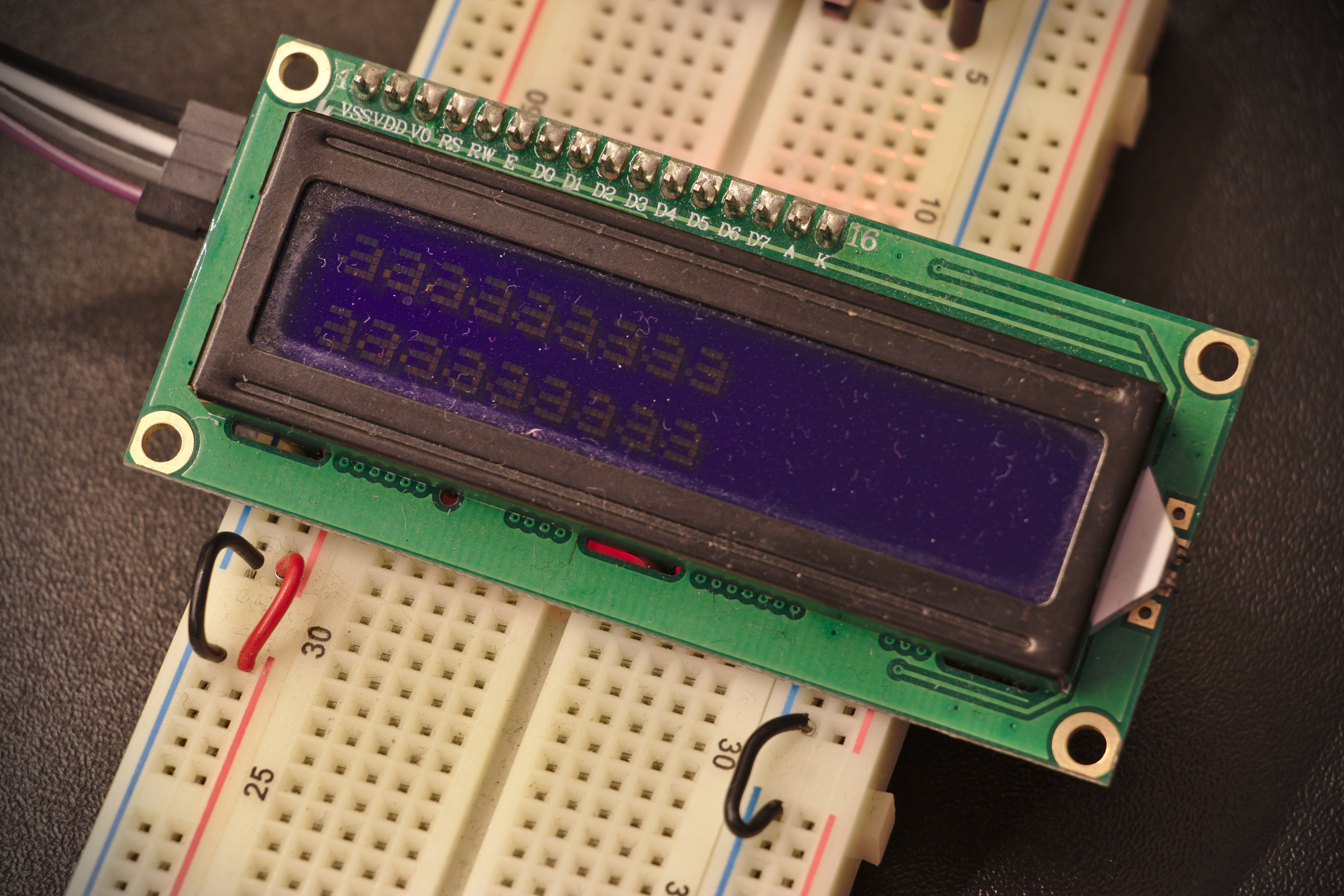
When we boot the board after configuring everything correctly in the device tree and activating the good driver in the kernel, the startup of the board will be very rewarding — as we will see the following message appear on the screen:
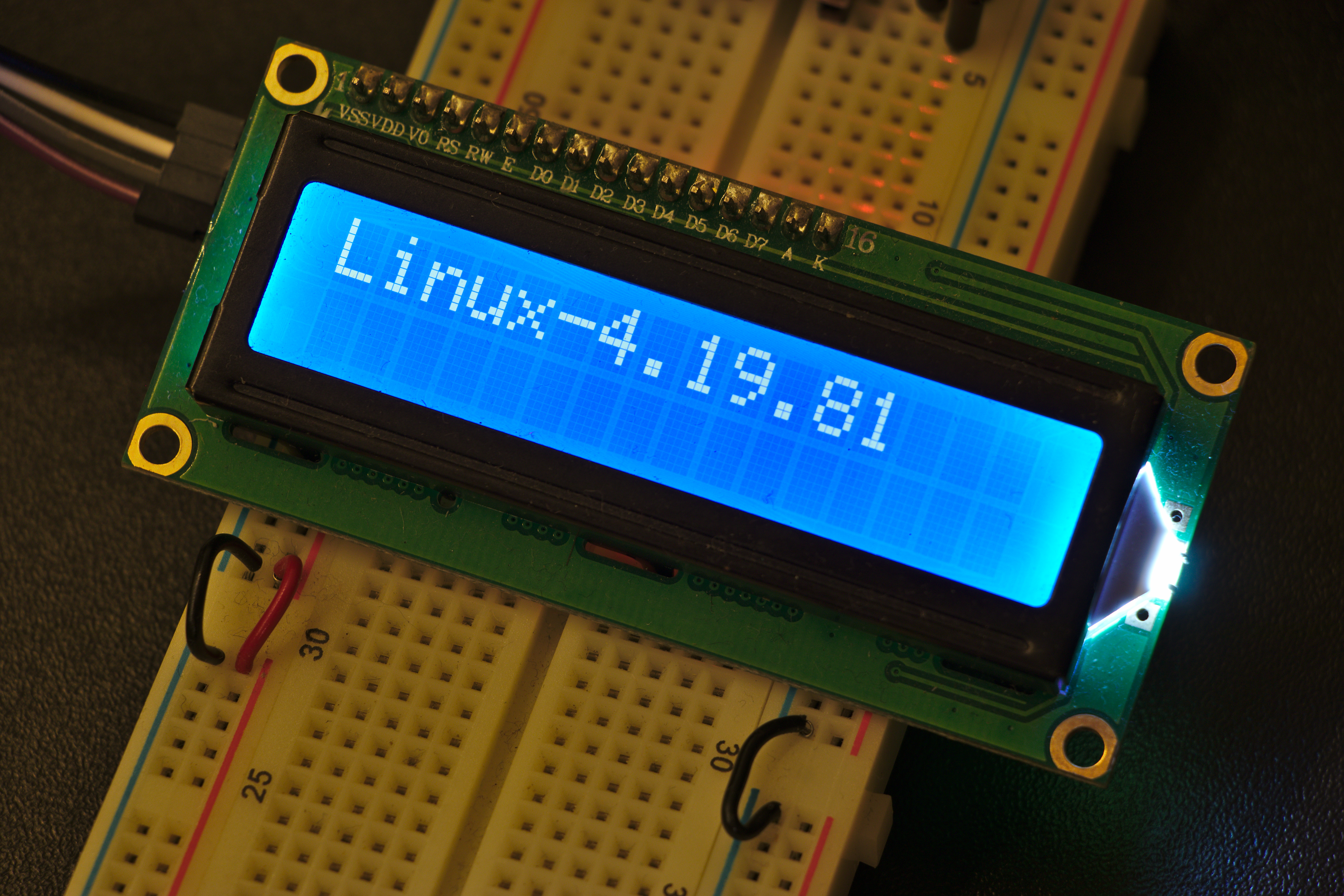
Yay, it works!
But wait, why is this appearing on the display?
Digging into the charlcd driver
Well, we can dig a little bit in the charlcd.c driver to find out what the driver does when it is probed:
/* initialize the LCD driver */
static int charlcd_init(struct charlcd *lcd)
{
    struct charlcd_priv *priv = to_priv(lcd);

...

    /* display a short message */
#ifdef CONFIG_PANEL_CHANGE_MESSAGE
#ifdef CONFIG_PANEL_BOOT_MESSAGE
    charlcd_puts(lcd, "\x1b[Lc\x1b[Lb\x1b[L*" CONFIG_PANEL_BOOT_MESSAGE);
#endif
#else
    charlcd_puts(lcd, "\x1b[Lc\x1b[Lb\x1b[L*Linux-" UTS_RELEASE "\n");
#endif
    /* clear the display on the next device opening */
    priv->must_clear = true;
    charlcd_home(lcd);
    return 0;
}
We can see that the message Linux-4.19.81 is displayed from this function — but more importantly we can see that the driver author also provided a way to customize the boot message using… a configuration option too!
We can try to activate this option using ARCH=arm make menuconfig in our kernel tree and search for CONFIG_PANEL_BOOT_MESSAGE.
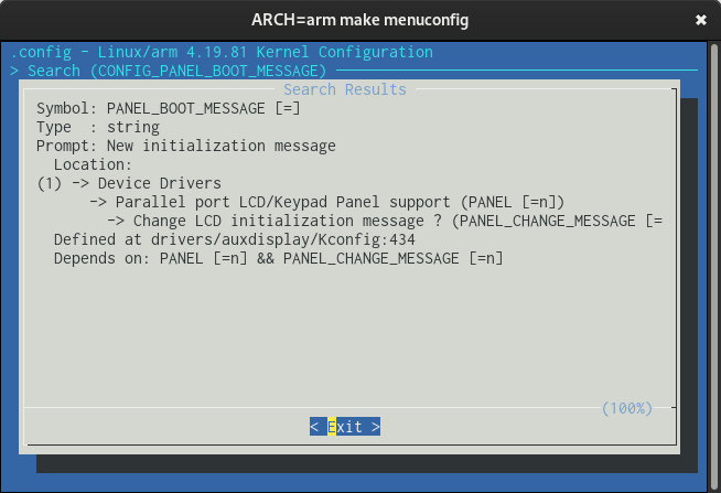
Searching for CONFIG_PANEL_BOOT_MESSAGE in Linux 4.19 using menuconfig
We can see that this option depends on activating the CONFIG_PANEL option which will activate support for parallel screen panel. By factorizing this option, the author does not let us the possibility to modify the message without activating an unrequired driver in our kernel. This is why I will not activate this option to change the boot message, as Linux-4.19.81 displaying at boot is not a problem for my intended purposes, and this is just for the boot time. As soon as our userspace program will be started, then we can print whatever we want on the screen.
We can observe that automatic messages are printed onto the screen as Linux starts on the board — but also when we request a system shutdown or reboot!
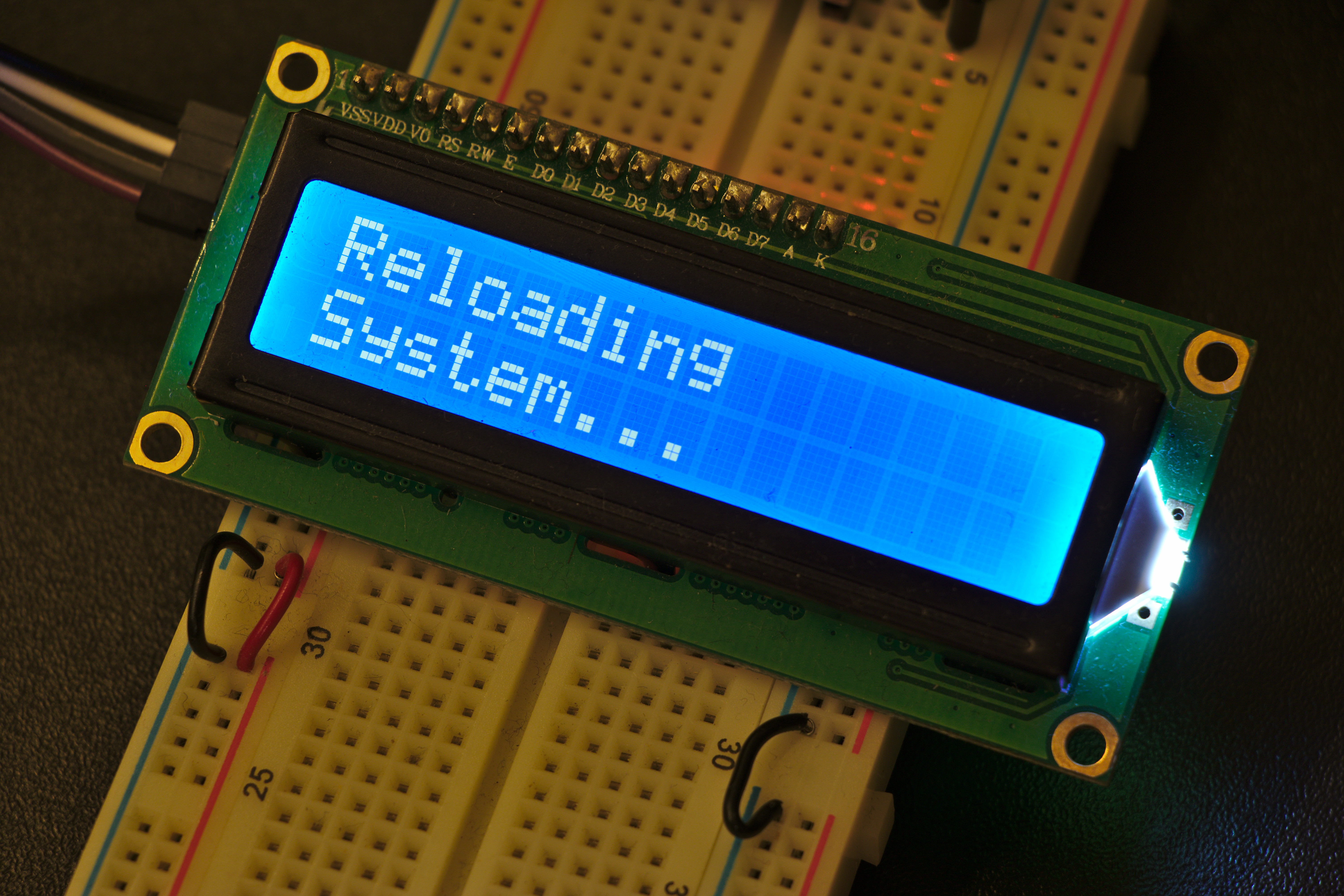
Interresting, how does this work?
Again, looking in the code of charlcd.c driver shows us that the driver is registering the panel_notify_sys function to the operating system, which will be called when a system event arrives — like when we call reboot or poweroff on the terminal using the serial console.
static int panel_notify_sys(struct notifier_block *this, unsigned long code,
            void *unused)
{
    struct charlcd *lcd = the_charlcd;

    switch (code) {
    case SYS_DOWN:
        charlcd_puts(lcd,
             "\x0cReloading\nSystem...\x1b[Lc\x1b[Lb\x1b[L+");
        break;
    case SYS_HALT:
        charlcd_puts(lcd, "\x0cSystem Halted.\x1b[Lc\x1b[Lb\x1b[L+");
        break;
    case SYS_POWER_OFF:
        charlcd_puts(lcd, "\x0cPower off.\x1b[Lc\x1b[Lb\x1b[L+");
        break;
    default:
        break;
    }
    return NOTIFY_DONE;
}
If you want to change the messages — for example to print them in another language like French — you could generate a small .patch file and pass it to Bitbake for it to patch your kernel with the newer strings before compiling it.
Using it in userspace
Now that the hard part — configuring the kernel and the device tree — is done, we can very easily print stuff on the screen by just writing to the /dev/lcd file.
By reading the driver's source code (again), we can find all of the supported special characters and escape sequences. As my needs are quite modest for the sake of this example, I will just use the \f special character to clean the screen.
Here is a proof-of-concept shell script that will alternate the printing on the screen to show me the next departures of my local transportation infrastructure.
#!/bin/sh

scrn() {
    printf "$@" > /dev/lcd
}

scrn '\f'

while true; do
    scrn '17 PARIS SRLC 12\n'
    scrn '02 IGNY ORSAY 08\n'

    sleep 5

    scrn '24*PARIS SRLC*19\n'
    scrn '11*IGNY ORSAY*16\n'

    sleep 5
done
This code is pretty straightforward, and we can use a POSIX shell script for prototyping thanks to the abstraction that the kernel provides by this simple /dev/lcd file. Of course, the final application will probably be written in Python instead of shell script, in order to access to the realtime SOAP API (or scrap HTML, if the access I have requested is not answered).
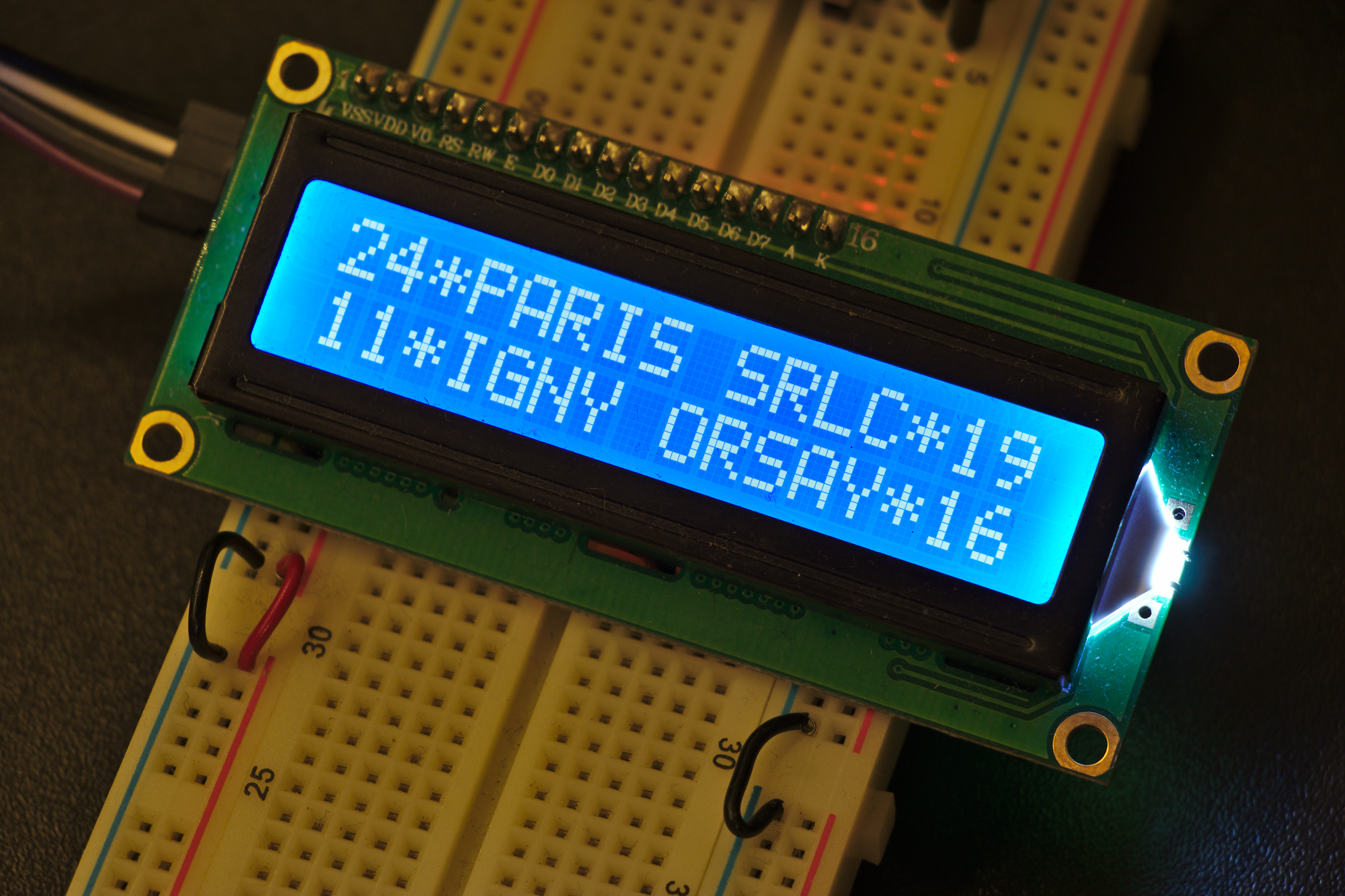
The star symbol indicates that times are for the trains after the next one.
Special codes
This code detects the start of a special code sequence:
#define LCD_ESCAPE_CHAR        27    /* Use char 27 for escape command */

...

/* codes starting with ^[[L */
else if ((priv->esc_seq.len >= 3) &&
     (priv->esc_seq.buf[0] == '[') &&
     (priv->esc_seq.buf[1] == 'L')) {
    processed = handle_lcd_special_code(lcd);
}
And in the function handle_lcd_special_code we can see all of the supported stuff, for example for the backlight:
case '+':    /* Back light ON */
    priv->flags |= LCD_FLAG_L;
    processed = 1;
    break;
case '-':    /* Back light OFF */
    priv->flags &= ~LCD_FLAG_L;
    processed = 1;
    break;
case '*':    /* Flash back light */
    charlcd_poke(lcd);
    processed = 1;
    break;
So, how do we use it in userspace? Well, we first need to output character number 27, followed by [L and then the special character. I need to find out what 27 is in hexa to use it using echo -e '\x00' but with the correct number instead [2].
For this, we can use the universal calculator, Python.
>>> hex(27)
'0x1b'
Great, so now we can write some functions to play with the screen.
lcd_special() {
    echo -e "\x1b[L$1" > /dev/lcd
}

backlight_on() {
    lcd_special +
}

backlight_off() {
    lcd_special -
}
And I will stop here for the userspace part. I guess you get the idea.
| [2] | You probably want to use printf '\x00' instead of echo -e '\x00', as the later is not POSIX-compatible. I figured this out after the article was written, so I will not change the code snippets here. |
That's it? Future hacks and tweak
The "too bright" issue
We often discuss these little screens at the local radio club which I am part of, and most of us agree on how cheap these screens are and how well they can replace discrete LEDs to display information — but also how bright they can be in a dark room. One solution we have considered would be to replace the brightness jumper present on the screen with a small variable resistor.
This little jumper here could be replaced by a THT variable resistor.
The value would have to be determined by increasingly putting a fixed resistor until the backlight is gone, and then now that we have the max value we can pick a variable resistance which will allow us to vary between 0 and MAX ohms, resp. full and no brightness. If we want to be able to adjust the brightness live on the instrument, then using a full blown potentiometer is a solution — but it will imply more mechanical work than just soldering two pins of a THT component on the back of the screen.
Considering different colors?
Another solution to reduce eye strain is to avoid the white/blue variant and to prefer the green/yellow screen one. Agreed, this color combo looks vintage (because it was the first?), but to me it looks less aggressive than plain white and blue. While reading the text with the backlight off on the blue variant is hard, we all remember that reading on an non-backlit green/yellow LCD screen can be achieved without much effort.
This is not very legible — and yes, the screen is a bit dirty.
I would say it depends on the hack being conducted: keep the green/yellow screen for your own hacks that stay home, and use the blue/white one for impressing other people by presenting your very cool IoT device (whoops, mine uses an Ethernet cable, is it still IoT?).
Getting a little bit more room
The 16×2 characters variant is the cheapest on the market, but you will soon feel quite limited in the quantity of information that you can display at once. Implementing a paging system to sequentially display some information after a small delay will not be pleasant to the eye, as the redraw of the screen takes a noticeable amount of time.
Another solution, if you mechanics budget (ie. available room on the front panel) allows it, is to choose a bigger screen with the same protocol to display more information at once — and avoid the paging system altogether. Here are the current prices that I have found on the Chinese market for the different variants:
| Size | White/Blue | Green/Yellow |
| 16×2 | €2.49 | €2.03 |
| 20×4 | €3.48 | €3.48 |
If you need even more room to display more text, then one should consider a pixel screen instead of an alphanumeric one. This will allow you to print more information by using tiny pixel-perfect fonts, but you will have to be quite close to read it comfortably. On the software side, it will be a bit more complicated, given that you will have to handle the framebuffer somehow to control what pixels to activate to make it print text.
Let's hope a driver exists for this in the kernel! But that's another story.
Conclusion
This experiment went quite well — as I am getting more and more familiar to Linux drivers and device-tree usage thanks to my current job, which quite matches with my personal hacking interests. Without this acquired experience, I would have probably hooked it to a Raspberry Pi (because god knows why this seems to be the only Linux SBC used by hobbyists) and use a userspace library to do the job — and probably fry it because I would have forgotten the logic level converter in the first place (thanks, robotic club's cemetery!).
I hope that I will be able to purse my IoT project (using the bigger yellow/green screen?) to display the next arrivals of public transportation near my place. No more smartphone unlocking, app starting, destination entering and such — just look at the screen and prepare yourself to go because the next train is in 10 minutes and you've got a 7 min walk to get there. This will probably save me 30 seconds of tiring smartphone manipulations each time I want to check the next departure.